What Is a Cable Assembly?
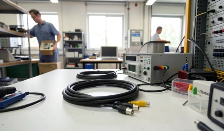
A cable assembly is one or more cables terminated with connectors or other interfaces and packaged to carry power, signals, or data between defined points. It is a finished interconnect, unlike bulk cable or a collection of loose conductors, contacts, seals, and connectors.
The assembly may include a jacket, braid or foil shielding, strain relief, labels, overmolded transitions, seals, and mounting hardware. Each feature should serve the drawing and operating environment. A buyer therefore specifies the complete electrical and mechanical interface rather than ordering cable by length alone.
The endpoints define what the assembly must connect, while routing, flexing, temperature, fluids, electromagnetic exposure, and installation space shape its construction. A useful specification also states how the finished unit will be inspected, tested, identified, and accepted.
What Is Wire Harness Assembly Compared with Cable Assembly?
The terms overlap, but cable assembly often emphasizes jacketed or connectorized cables, while wire harness assembly organizes multiple discrete conductors into a routed bundle. Suppliers and industries use the labels inconsistently, so function, drawing, environment, and acceptance criteria matter more than the label.
These are tendencies, not hard boundaries. A single drawing can contain shielded cable legs, discrete wires, branches, and a common connector. The RFQ should describe the physical build and required evidence clearly enough that two suppliers quote the same deliverable regardless of the name used.
What Types of Cable Assemblies Exist?
The main types covered here are overmolded assemblies, coaxial or RF assemblies, and box-build or integrated assemblies. They differ in construction, use, design priorities, and the validation needed to show that the finished interconnect meets its drawing.
Overmolded cable assemblies
Overmolding forms a protective body around a termination, splice, or cable transition. Material selection should reflect flexing, temperature, chemical exposure, sealing needs, cable-jacket compatibility, and the required strain-relief geometry. A sealed-looking part is not proof of an ingress rating, so the buyer should define the test method and acceptance level.
Coaxial and RF cable assemblies
Coaxial assemblies control the relationship between the center conductor, dielectric, shield, and connector to transmit high-frequency signals. Cable type, characteristic impedance, bend limits, connector launch, assembly length, and termination quality can affect RF performance. Shield construction helps manage electromagnetic interference, but required attenuation and coverage must be specified for the application.
Box-build and integrated assemblies
An integrated assembly combines cable interconnects with items such as circuit boards, power modules, switches, or enclosure hardware. Its drawing package must control both the cable interfaces and their installation into the enclosure, including routing, fastening, clearances, labeling, and final functional test.
How Are Cable Assemblies Built?
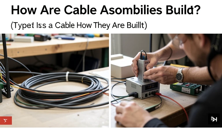
Cable assemblies are built through a controlled sequence of requirements and bill-of-material review, preparation and termination, protection or overmolding, identification, inspection, and test. The exact operations depend on the drawing, approved components, termination method, operating environment, and acceptance plan.
- Review requirements and the BOM: Confirm interfaces, cable construction, dimensions, materials, revisions, approved sources, test limits, and documentation before releasing work.
- Prepare and terminate: Cut, strip, crimp, splice, or solder according to controlled instructions that protect conductors, insulation, shields, and seals.
- Add protection: Apply jackets, braid, heat-shrink, boots, potting, overmolds, or hardware where the drawing requires them.
- Identify the assembly: Add part, revision, lot, orientation, and serial markings needed for installation and traceability.
- Inspect and test: Check workmanship, dimensions, pinout, electrical behavior, mechanical retention, and any application-specific performance.
Tooling and crimp controls
The build package should identify the applicator, die, locator, calibration status, setup method, and process checks for each controlled termination. A contact and wire combination may require crimp-height, pull-force, or force-monitoring controls. Recording the method prevents an operator from choosing tooling solely because it appears to fit.
Approved components and first-article review
Approved manufacturer part numbers and substitution rules keep contacts, seals, housings, cable, and accessories aligned with the design. A first-article review should confirm dimensions, materials, routing, marking, workmanship, and test records before production volume increases. Any applicable workmanship or validation documents should be identified by revision, with standards context checked through the SAE standards catalog when relevant.
How Are Cable Assemblies Tested?
Cable assembly testing is application-specific and should verify the electrical and mechanical requirements on the drawing. The test plan must state methods, limits, sampling or test frequency, equipment, record format, and the response to a failure.
A pass result has meaning only when tied to the correct drawing revision and acceptance limit. Buyers should also define whether records are required per unit, per lot, or only for sampled validation. Retaining raw values can support trend review, while a simple pass label may not reveal a drifting termination process.
What Should a Cable Assembly RFQ Include?
A usable cable assembly RFQ needs drawings, a BOM, conductor and connector requirements, environmental conditions, quantities, workmanship criteria, testing, and traceability. It should also define revisions, approved sources, substitution authority, sample approval, and the records delivered with the order.
Gauge, materials, and traceability
Specify every conductor by material, gauge, stranding, insulation, voltage or temperature requirement where applicable, color, and approved source. A published gauge range is not confirmation that a supplier has the correct tooling and validated process for a particular wire-terminal pair. Require written gauge-to-process confirmation, approved-source records, material certificates where needed, lot traceability, and a clear link between records and delivered assemblies.
For example, WellPCB’s own pages publish conflicting wire-gauge ranges, so buyers should not treat one range as a definitive capability. Its published manufacturing and RFQ capabilities from WellPCB should be checked against the actual drawing, conductor list, process mapping, and requested evidence for the order.
Approved connectors and substitutions
List manufacturer part numbers for connectors, contacts, seals, backshells, and accessories. The company states that it works with Molex, JST, TE Connectivity/AMP, Hirose, Deutsch, Amphenol, and other named connector brands, but that statement does not establish a partnership or authorized-distributor status. Buyers can use the TE Connectivity connector reference to resolve series and component choices, then require source documentation and written approval before any substitution.
Revision control, samples, and records
State which drawing, BOM, test specification, and workmanship revision controls the quote. WellPCB describes itself as a custom wire-harness and cable-assembly manufacturer with facilities in Shijiazhuang and Shenzhen, China, and states that it builds to IPC/WHMA-A-620 Class 2/3 workmanship. These are brand claims, so the purchase package still needs the applicable workmanship class, inspection points, and objective acceptance records.
Define first-article quantity, approval authority, change notification, production release, and retained sample needs. Manufacturer-published WellPCB processes include cutting and stripping, crimp-force-monitored termination, ultrasonic splicing, soldered terminations, overmolding, marking, and barcode serialization. The company also publishes 100 percent continuity, hi-pot up to 1500 V DC, insulation resistance of 100 MOhm at 500 VDC, and data logged per serial number. Those values are manufacturer-published examples, not universal pass criteria, so the RFQ must state the limits and record frequency required for this design.
For automotive work, manufacturer-published examples include pull-force minimums of 50 N for signal and 100 N for power, SAE J2030 crimp validation, and crimp-height verification to plus or minus 0.05 mm (0.002 in). Do not copy these limits into another program without engineering review. For medical work, the company claims ISO 13485:2016 certification; buyers should verify the certificate, its scope, and current status directly.
How Do You Cost Down a Medical Cable Assembly?
Cost reduction for a medical cable assembly should remove unnecessary complexity and supply risk without weakening validated requirements or traceability. Every proposed change should pass documented engineering and quality review before it affects materials, tooling, inspection, testing, or released production.
- Review connector availability: Identify long-lead or single-source parts and assess approved alternatives early, including contact, seal, mating, keying, and regulatory implications.
- Recheck conductor selection: Confirm that gauge, strand construction, insulation, shielding, and flex life match actual loads and use conditions without adding unsupported margin.
- Challenge tolerances: Relax only dimensions that do not affect fit, function, safety, routing, or validation. Tight limits can add inspection and scrap without improving the device.
- Simplify overmold design: Reduce avoidable geometry, inserts, color changes, and material variants while preserving strain relief, sealing, cleanability, and biocompatibility requirements where applicable.
- Use common approved components: Consolidating qualified wire, contacts, labels, and hardware can reduce purchasing complexity and obsolescence exposure.
- Rationalize tests by documented risk: Remove duplicate inspection only when engineering and quality evidence shows coverage elsewhere. A lower test level is not acceptable merely because it costs less.
- Model tooling amortization: Compare tooling investment against realistic program volume, change risk, maintenance, and expected product life.
- Improve forecast visibility: Stable forecasts can support material planning and economic batch decisions without forcing an unapproved component change.
Evaluate each idea through formal change control, including updated risk analysis and any required revalidation. The most durable savings usually come from a clearer specification, fewer unique items, and better supply planning rather than reduced evidence or weaker acceptance criteria.